In this tutorial we will be integrating If This Then That(IFTTT) into our smart garage setup and with it create a smart garage door opener that can be controlled by a mobile phone.
Application
Knowing how to control devices like a garage door opener from a mobile device has huge implications. Imagine for a second you had to suddenly leave the house and forgot you had food on the stove cooking. If the stove were hooked up to an embedded system you could receive a notification when you get far away from the your home that the stove is still on and turn off the stove from a remote location. Also think about how useful being able to control your garage from anywhere could be. You could let your kids into the house even if you’re not home. You could set up a geofence to automatically close the door if you forget and start driving away. The possibilists here are endless.
What is IFTTT?
The number of technologies that exist in the world continues to increase and IFTTT is dedicated to making all that tech work together in harmony. For example, phone might be made by Apple and your TV by Samsung. IFTTT makes it so that you can control the TV through your Apple device. For the more advanced, IFTTT allows you to call the API that devices have and connect those to other devices’ APIs.
How does the Relay Work?
The way we integrate our cell phone into our smart garage setup is fairly simple to understand. The IFFTT app is going to use what’s called a webbooks to alert a server to open the garage door and the relay will be listening to that server and toggle the state of the garage.
Materials Needed
Wemos Relay Shield
Wemos Micro Controller
Arduino D1 Mini
Breadboard
Wires
Mobile Device (preferably phone)
Procedure
Let’s start by getting setting up the external software.
With the number of IOT devices ever increasing, having an easy to use dashboard to both control and visualize the states of IOT devices is an extremely valuable piece to have in any embedded system.
Application
IOT devices are powerful but not intuitive to use for the average consumer. Creating a dashboard allows the average joe to take full advantage of these devices. For example using a dashboard an average joe can control an IOT security system installed in their house and see whether the doors are locked or potentially lock all the doors in the house at curfew so that teenagers who come home late have to sleep in the garage (true story).
Materials
To complete this lab, you will need the following materials:
· A Raspberry Pi with a bootable SD card
· A Raspberry Pi power supply
· A computer with a SD card reader and a MQTT broker installed
The following links may be helpful to compelte this tutorial:
· http://aaronnelson95.com/IT441Lab4.php – Lab 4 Instructions on how to set up the Mosquitto MQTT broker on a computer and how to develop 3 Arduino devices to communicate with MQTT
1. Setup the Door Opener, Echo Sensor, and Stoplight devices from Lab 4. In addition, you should have a Mosquitto MQTT server running. Verify that these devices work together and that they publish data to the following MQTT topics. This information will be used and read by Home Assistant:
a. Download the latest Hassbian image and flash the image onto an empty SD card.
b. Insert the card into a Raspberry Pi and either plug it into a monitor with a keyboard and ethernet cable or configure your Pi’s wireless network by altering a file in the boot partition (as explained in the guide).
c. Wait several minutes for the latest version of Home Assistant to be installed. When prompted, you can login to Hassbian with the default username of “pi” and password of “raspberry” (or you can SSH right into the Pi with its IP address if you are doing this without extra peripherals). When the installation is finished, you should be able to see some files populated in “/home/homeassistant/.homeassistant/”.
d. Type in “$ sudo raspi-config” to change the default password. You can also add a wifi network here and adjust other settings. If you would like to set multiple wifi networks for your device (I would highly recommend running it off of a hotspot hosted by the same computer your MQTT server is on), you can set those in the “/etc/wpa_supplicant/wpa_supplicant.conf” file.
e. Using a device on the network, open a web browser and go to “http://<YOUR_PI_IP_ADDRESS>:8123”. If Home Assistant appears, set an initial account up to log in with. If it does not appear, follow the troubleshooting steps in the Home Assistant instruction guide. Once you are in, you should see the main Home Assistant page, where you will add cards to for monitoring MQTT data.
Seeing the Home Assistant page come up is an indication that the installation worked
3. Add the MQTT Integration to Home Assistant to be able to work with your Mosquitto Server. This can either be done through the UI, or by editing the configuration yaml file for Home Assistant. Change this file with the command “$ sudo nano /home/homeassistant/.homeassistant/configuration.yaml” (we will be editing this file frequently throughout the lab). Simply insert the code below to connect to Mosquitto hosted at your Mosquitto server’s IP:
# Sets up the MQTT broker, which in this case is my computer’s Mosquitto servermqtt: # The IP of the Mosquitto server broker: 192.168.137.1 # What the Home Assistant client should check in as client_id: homeassistant discovery: true # The MQTT Topic to watch (subscribe to) discovery_prefix: garage
Afterwards, restart home assistant with the command “$ sudo service home-assistant@homeassistant restart” (this will also be done frequently, so memorize this command!). In the browser, under the Configuration tab and then Integrations, you should now see a listing for “MQTT: configuration.yaml”. You can test that this works by going to the Developer Tools tab, selecting MQTT, and then listen to the topic “#”, which should then populate when you use your Arduino devices.
4. Now that Home Assistant is connected to the MQTT server, the topics will be setup as different sensors. In Home Assistant, once a topic receives a different value, the sensor will reflect and also contain that value. This is done by editing the configuration.yaml file again and then restarting the Home Assistant service. You will add the following for each topic you wish to watch:
sensor: # Directly returns the value of garage/doorSwitch (a 0 or 1) – platform: mqttname: “Door Switch MQTT”state_topic: “garage/doorSwitch”
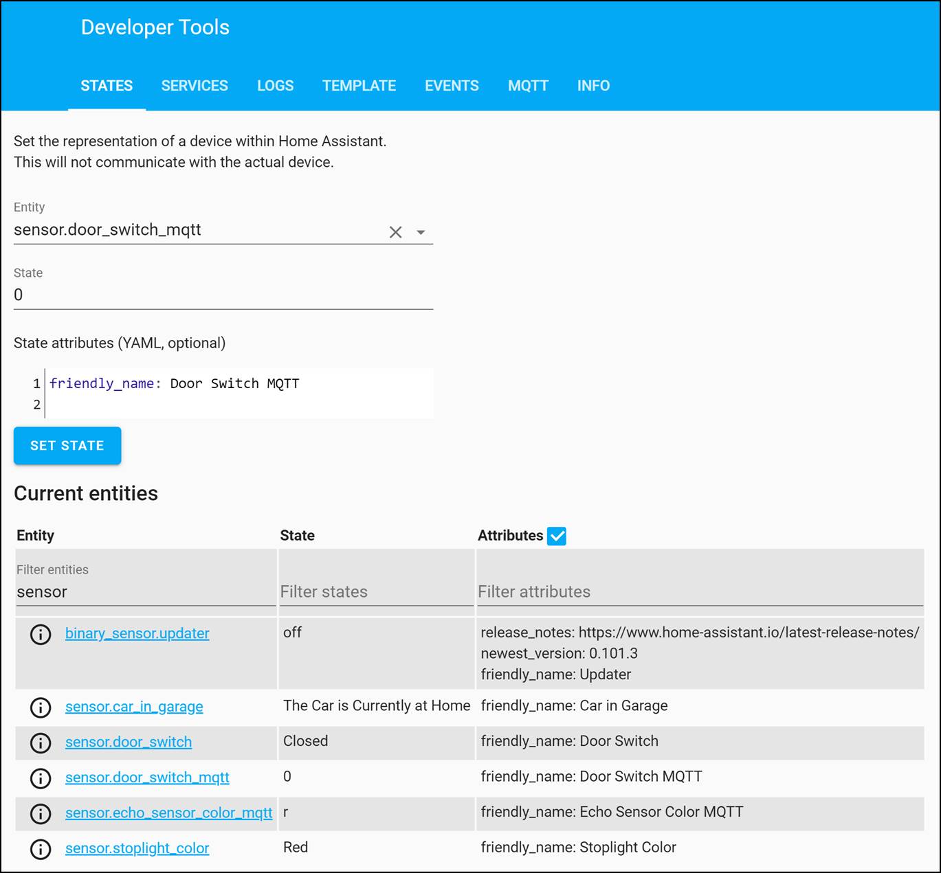
5. Because the MQTT sends simple values, it may be beneficial to create another sensor that uses a template to assign friendly names to these topics. This will create another sensor device, and will not alter the original MQTT feed. To test the syntax of any template, you can go to the Developer Tools tab of Home Assistant and then select Template. You can examine if your code works like you intend. In addition, under the Developer Tools, you can also select the States tab to view your sensors. As you adjust MQTT values, the state column for the sensor entity will change here. Create an easy to read sensor by following this example:
sensor: # A template “adjusts” the values from a MQTT sensor to make it more readable and user friendly # This makes the Door Switch MQTT either return “Opened” or “Closed” – platform: templatesensors:door_switch:friendly_name: “Door Switch”value_template: >-{% if is_state(‘sensor.door_switch_mqtt’, ‘1’) %}Opened{% else %}Closed{% endif %}
Viewing MQTT Sensor Values in Developer Tools -> States
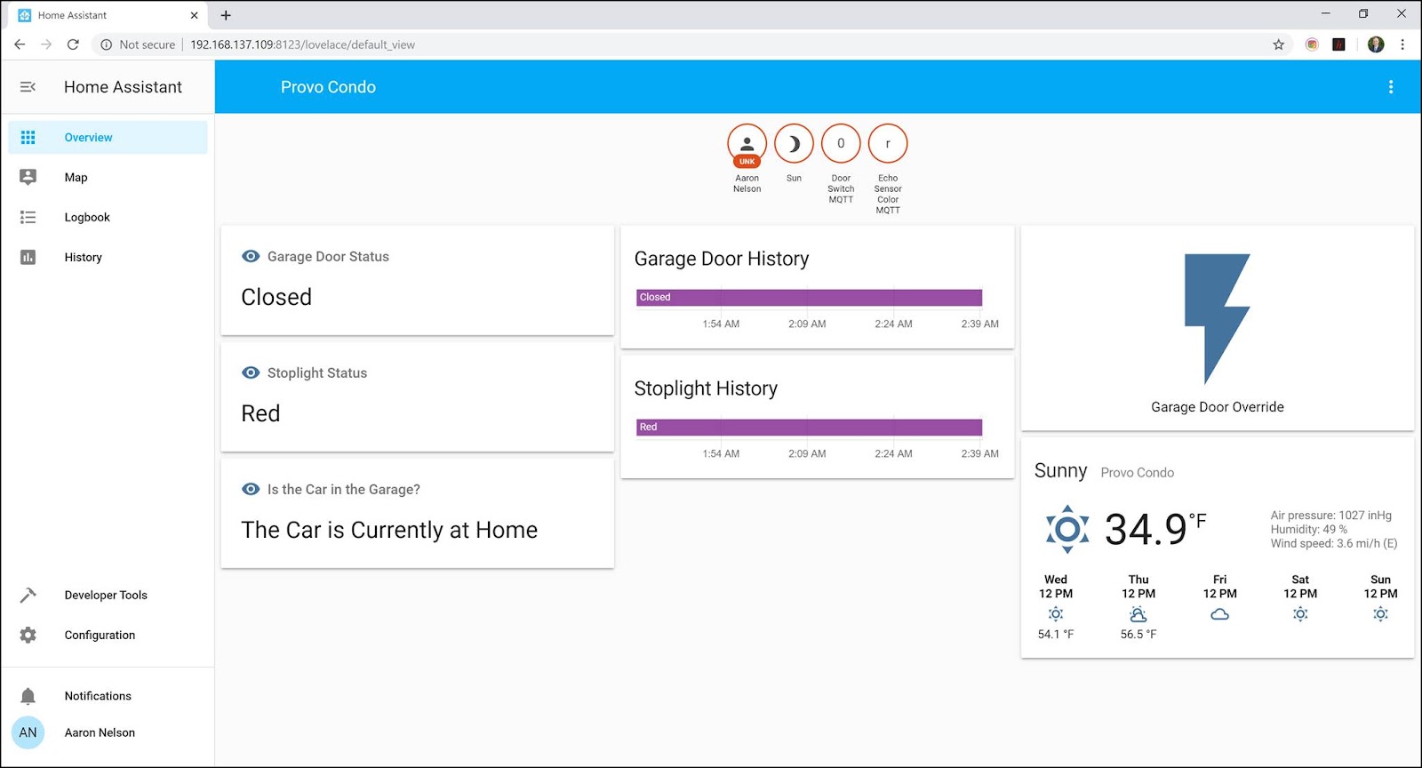
6. Now that we have sensors reading data from the MQTT broker, we can add cards to the Overview tab of Home Assistant to view this data easily at a glance. In this tab, click the three dots in the top right corner and select the option to configure the UI. In the bottom right, click the + button to add a card. To display the sensor data plainly, select the Sensor card. The Entity will be the name of your easy to read sensor and you can adjust other properties here. Feel free to test out other cards as well, such as the history graph. When you make changes and add cards here, they are recorded to a JSON stored in /home/homeassistant/.homeassistant/.storage/lovelace. Alternatively, you can manually insert card data in the code here.
Home Assistant Overview showing Sensor Values, histories, and other cards
7. Experiment with other sensors devices and cards. For example, I used a “switch” to listen to a MQTT topic. It also provides a button I can push to post a value into that topic as well, acting as a “manual override” mode for my garage door switch. I also created a sensor with a template to show whether or not my car is parked in the garage based on sensor readings.
Images of Final Product
Our Mosquitto Server is properly setup from Lab 4. It listens to values passed by the Arduino devices
When our devices are running and the distance from the sensor is relatively close, home assistant shows the current color of the stoplight, if the garage door is opened,
and whether or not the car is likely still at home. Also, the garage door override button lights up, showing it is opened and that we can force it to close.
I can also view a detailed history of my sensors and states in Home Assistant
Ubiquitous Computing is the idea that computers and electronics are being seamlessly integrated into everyday life. This tutorial will show you how to do that with a garage setup. First we’ll be implementing a door sensor to alert the system of whether or not the garage door is open and then we’ll look into MQTT as a way to connect several IOT devices asynchronously across a network.
Application
A door sensor can be useful in several ways but the more important application is the MQTT broker. Being able to keep IOT devices in sync around a network can be extremely helpful. Imagine for a second you have a IOT security system. The moment the alarm is trigger an MQTT broker can send every device on the network into the lockdown protocol at the same time. Or using this method an array of lights around the house could instantly be turned off. The applications of multiple devices in sync is endless.
How does the Door Sensor work?
When the the two parts of the sensor are together the sensor reads as closed but once the sensors separate the sensor reads as open and sends the necessary message to the network.
How does MQTT work?
The easiest way to explain MQTT is to think of it like YouTube. On YouTube you can subscribe to a channel and can hit a small bell to be notified when ever the channel publishes a video. Conversely, if you don’t hit the small bell icon you won’t be notified. And finally based on the video and it’s content you decide whether or not to watch the video. MQTT is very similar. IOT devices are connected to a MQTT server and subscribe to certain topics and are notified when one of those topics is published. Based on the message that comes with the topic the IOT device can execute a function. Here’s a graphic showing how that would work on a thermometer system:
In the case of our IOT garage setup the door sensor publishes to the garage topic and the distance sensor turns on only if that published topic has the message “open”.
Materials Needed
RaspberryPi
Arduino D1 Mini
DC 1561 Surface Mount Alarm
Computer
Hardware Setup
Let’s get the Surface Mount Alarm Setup
The end result should look something like this:
grab the Arduino D1 Mini and the surface alarm
connect one of the surface alarm wires to a pin on the d1 and the other to the Arduino GND pin.
Plug into the computer and get ready to code.
Code Setup
Before explaining the door sensor code there is some code that should be added to ultrasonic sensor. The code added enables the sensor to only turn on when an MQTT message says that the garage door is open. For the rest of my ultrasonic setup check out the tutorial here. In the end the MQTT interaction will look like this:
Now for the door setup. The idea is very simple when the device turns on it will connect to the MQTT server. Then it will publish a message to the garage topic on the status of the door. If the sensor shows as closed then publish closed, if open publish open.
One Arduino can do lots of cool stuff but connect them over the internet and you can do tons of cool stuff. In this report I’ll be showing you how to use an ultrasonic distance sensor to measure distance and use that distance to trigger a stop light light indicator.
Application
A distance sensor with indicator can have many application. One application is indicating when you should stop your car when pulling into a garage. In the COVID-19 pandemic you could use this distance sensor and indicator to show whether people are properly social distancing. The possibilities are endless.
How does it work?
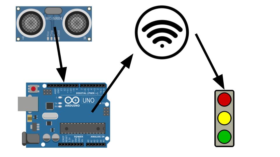
The Arduino is connected to a HC-SR04 ultrasonic sensor that uses technology very similar to echolocation to measure the distance between itself and objects. The distance measured by the sensor is sent to the Arduino which is programmed to send a http request based on the distance measured over the WiFi connection to the the traffic light indicator. The traffic light then indicates to the person whether they should continue moving forward, slow down, stop or back up. This relationship is represented in the diagram below.
To understand how the traffic light indicator works go check out my last post here.
Let’s get the Distance Sensor setup with the Arduino
The end result will look like this:
Grab all the materials necessary except the traffic light indicator and your computer
Pick a place on the bread board and insert the Ultrasonic Senor so that the four pins are each on different rows.
Now connect a wire from the row with the VCC pin and connect it to the 5V pin on the Arduino
Pick two pins on the Arduino to be your Echo and Trigger pins and connect wires to the breadboard accordingly.
Finally connect a wire from the GND pin to the G pin on the Arduino
The final result should now look like similar to the diagram above.
Code Setup
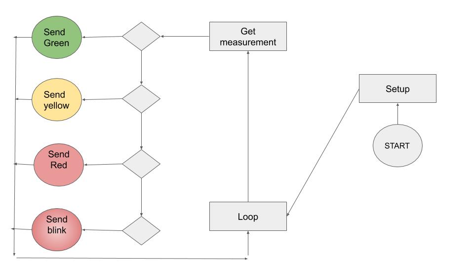
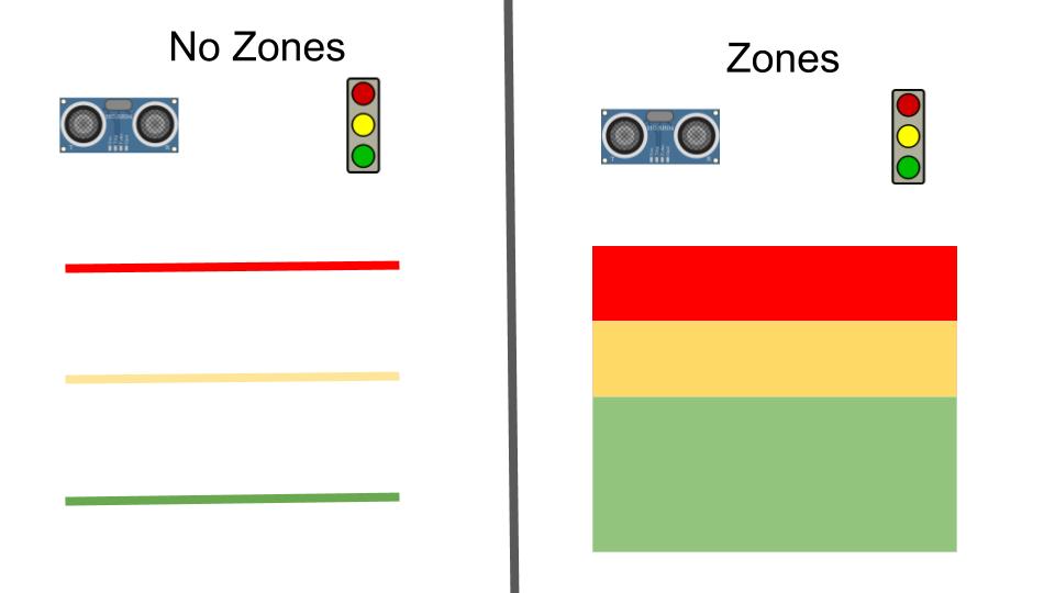
The code is going to be looping through the readings sent from the ultrasonic sensor and storing it as a variable. From there we will manipulate the variable to be in the desired form of measurement and we will use that measurement check if the object in front of the sensor is in one of the zones predetermined zones. Depending on which zone the object falls under will determine which HTTP request is sent to the Traffic Light Indicator.
Why zones? Precise measurements are very hard to get to and in the case of parking a car or properly social distancing you don’t need to be extremely precise. By using zones we ensure that the object is within an expectable range of distance rather than being at the exact distance. The overall effect is the same.
Setting up Arduino IDE
Grab your computer
(This setup tutorial comes from jonathanblack.org)
Think of the interaction between your devices. How well would this scale to multiple devices? Is it easy to add another sensor? Another actuator?
Depends. Adding another sensor and actuator would work fine the issue becomes synchronization. Using the HTTP request method feel slow and would take time for each device added meaning that the synchronization would be delayed per device added.
What are strengths and weaknesses of the tennis-ball-on-a-string system that Don had originally?
It’s strengths are that it consumes no power nor requires a WiFi connection. The weaknesses of the system are precision and being properly notified when when to stop the car.
What are strengths and weaknesses of the IoT system that he developed? What enhancements would you suggest?
Strengths would be precision and a clear indicator of how to get to the right distance. Weakness are the required power and WiFi connection. Both are not always available.
What was the biggest challenge you overcame in this lab?
My biggest challenge with this lab was the HTTP requests. Initially I tried to send the requests via a curl command but that proved to be unprofitable. I then discovered the HTTPClient method and was able to get the requests working almost instantly.
Please estimate the total time you spent on this lab and report.
Arduino is a powerful microprocessor that can be programmed for I.O.T. purposes. In this report I’ll be showing you how I created a Stoplight using an Arduino that can be controlled over the internet.
Application
How could this technology be used? If Traffic Lights were controlled over the internet then light cycles could be adjusted for the time of day or for accidents and obstructions. In the world of COVID-19 an Internet Traffic Light could mean that workers don’t have to go out to the lights to program or maintain them which would reduce their chances of contracting the virus. Internet controlled Traffic Lights could be paired with machine learning so that they could time their cycles so that traffic flows at a smoother pace which in turn could result in less traveling time for you and me. All these possibilities start with Traffic Lights being controlled over the internet.
How does it work?
The Arduino is coded to connect to a WiFi network. Once connected the Arduino listens like a web server for certain requests to be made to it’s IP address. When the requests are made the Arduino will change the state of the Traffic Light. Once the change is made the Arduino sends an HTML page back to the requester showing what the state of the Stoplight is. Here’s a picture showing that interaction:
Materials Needed
Arduino D1 mini
Breadboard
wires
3x Resistors
3x LED Lights (Red, Yellow, Green)
Computer
Hardware Setup
To start let’s get the hardware setup:
Here’s what the end result will look like:
Grab all the materials listed in Materials except your computer
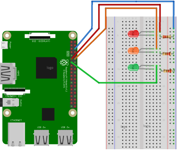
Choose a row on the bread board for each led
Place the led’s in the rows like shown in the diagram
Be sure the negative side of the LED is on the receiving end of power from the board
On the Arduino choose some of the pins that start with a “D” and write down which pins correlate to which light. (You’ll need this later in your code)
You can now connect a wire from the pin to the negative side of the LED
Now connect resistors from the positive side of each LED to what will be ground. In my example I choose to make a whole side row of the bread board to be used as ground.
Now connect the ground to the Arduino pin labeled with a “G”
Double check that everything is connected and in a closed circuit and you’re ready to start coding.
Code Setup
The code behind the Arduino Internet Traffic Light is fairly simple state machine illustrated by this state diagram:
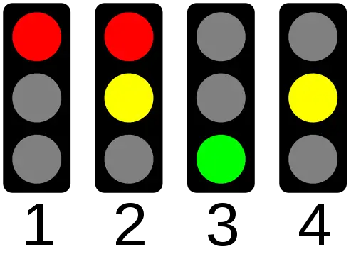
To put this state diagram into English terms the Arduino will start by having the Traffic Light stay in the Off state. The off state means that all LED’s are off. From this state the Arduino can put the Traffic light into several states. There is one state per LED where only that LED is on and the Arduino can put the light into any of those states from the off state. The other state which I refer to as Auto which basically puts the Traffic Light into a loop that transitions from Red state to Green state to Yellow state.
Setting up Arduino IDE
Grab your computer
(This setup tutorial comes from jonathanblack.org)
What are some key differences between developing this lab on a Raspberry Pi, and developing on Arduino?
For me the key difference was setting up the web server. The web server on RaspberryPi was much the same as the server I work with everyday at work but the Arduino required a different touch to get connected to the internet and listen for Requests.
What are the strengths and trade-offs of each of these platforms?
The Arduino is smaller and single purpose which to me means it can be more ubiquitous and is less of a security threat. This is also a limitation because any update you need to do to the IOT device using an Arduino needs to be done connected to the computer where as the RaspberryPi can be setup like a webserver and be updated from where ever. The problem with the webserver attributes is that the RaspberryPi then becomes a security threat that can be manipulated.
How familiar were you with the Arduino platform prior to this lab?
I once tried to help some engineering students get a 3D printer working that was made with Arduinos but I was not successful so I’d so little to none.
What was the biggest challenge you overcame in this lab?
Connecting to WiFi. I followed a really great tutorial for this lab but when it came to connecting to WiFi the tutorial wasn’t very clear on how to make that happen so I had to do a lot of research just to figure out that I had misspelled the SSID of my WiFi and once I fixed that I was able to connect to the Arduino over the internet.
Please estimate the total time you spent on this lab and report.
Like I said I found a really good tutorial for this lab and only spent around 2-3 hours on the actual lab. The report has been around the same amount.
The purposes of this lab are to: • Learn to utilize the general-purpose input/output (GPIO) pins on the Raspberry Pi to control LEDs. • Learn to develop a minimum viable product and deliver new functionality through subsequent updates until the requirements are met, and all of the deliverables are acceptable.
The setup of the RasberryPi and LED’s was using this Traffic Light Tutorial
The Flask Server was setup using this RaspberryPI Tutorial
Procedures
1. First let’s make sure you have ssh setup on your raspberry pi to do this you’ll need to connect it to a monitor mouse and key board. After it’s all connected open up the wifi settings and connnect to the wifi of you choice from there follow this Tutorial
2. Now that you have ssh setup ssh to your RaspberryPI and create a folder called webapp
3. We are now going to setup the python flask server using this Tutorial
4. Now that we are familiar with flask servers we are going to learn how to turn on and off the LED’s using this tutorial
5. Now comes the tricky part. Combining all three tutorials together to make one working stoplight over the python flask server. So in the python flask tutorial we learned that functions are executed based on what url is called. So what we are going to do is create paths for stop, slow, go, and cycle in the python server.
6. In the Raspberry Traffic Light Tutorial we learned how to make lights turn on and off so now we are going to add that code to the app.py file. So at the top of the file be sure to add the correct imports and then add the red, yellow and green variables defined by the pin they are connected to.
7. Now we need to create the routes for turning on each light and triggering the cycle. So add @app.route(“/stop”, methods=[‘POST’]) this will be our stop light trigger url. Under that code you can add “green.off() yellow.off() red.blink()” this will turn off the other two LED’s and make the red light blink. You can do the same for the other two methods. Now if you go in your terminal and type in “python app.py” a small webserver should start up. If you open a browser on a different computer and type in the ip address followed by “:5000/stop” the red light should start blinking
8. The cycle will be a little different from the other functions. First create app route for cycle. Once that’s created you are going to need to create a function that turns on a light waits for a few seconds and then turns it off and the next one on. And all this needs to happen continuously. To do this you can create a while loop. And under the while loop turn on a light using “green.on()” and then “sleep(number of seconds to wait)” and then turn off the light using “green.off()”. This will continue to happen forever. Once you have that code in you have a functioning Traffic light that works over wifi.
Thought Questions
What language did you choose for implementing this project? Why?
I decided to use python and python flask for the languages because there were super easy libraries ready to go for turning on and off the LED’s and the flask server was easy to use for executing python functions. I looked into using an apache server but executing the python code was going to be pain so I decide to go python all the way.
What is the purpose of the resistor in this simple circuit? What would happen if you omitted it?
My understanding of the resistor is to keep the amps at a bearable level for the LEDs. If too much amps go through the LED it will blow it up or in a less spectacular scenario burn it out.
What are practical applications of this device? What enhancements or modifications would you make?
So this simple device would make it really easy to change the light when needed. So if an ambulance needed to get through a light you could change it over the internet and make sure they get through A.S.A.P. If I were to modify the device I would want to make a way for the light timing to change based on the number of cars at an intersection or maybe have different cycles depending on the time of day.
Please estimate the total time you spent on this lab and report.
Lab: 4-5 hours Report: 2 hours
Certification of Work
I certify that the created solution represents my own work. I acknowledge openly that I borrowed code and gave credit where due. I also cited the resources used in this solution in the resources section.